Here you will find notes on some of the projects I have been working on.
As I am running Linux, not windows, some changes may be needed to get similar things to work.
Searching on the subject and asking in appropriate groups should help in this case.
All the original software on this page is covered under the GPL license and hardware design information under the Creative Commons Attribution-Non Commercial-Share Alike v3.0 license.
| | |
| |
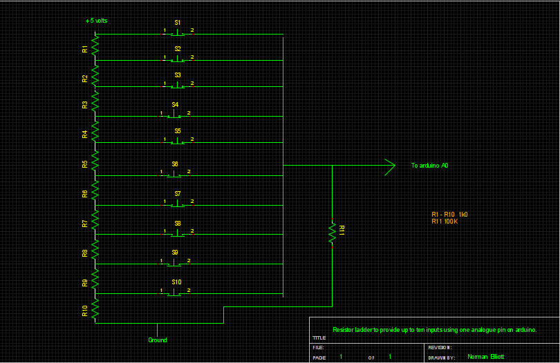
on 1 analogue pin | | | |
| | | ||
DS1307 | | | |
Information | | | |
Project | | |
Back to Top
Here is code to use an analogue input to provide up 10 different values corresponding to the pushbutton pressed. The resistors R1 to R10 need to be 1 percent tolerance and R11 needs to be 80 to 100 times the value of the others.
From what I have read 100K is about the maximum pull-down value which can be used but R1 to R10 can be lower values even down to 100R although it would use more current which might be too much for battery equipment.
[code]
void setup()
/* This outputs to the serial monitor for demo purposes */
{
Serial.begin(9600); // activate the serial output connection
}
int divider=100; //for 10 buttons
//int divider=125; //for 8 buttons
//int divider=200; //for 5 buttons
//int divider=250; //for 4 buttons
//int divider=333; //for 3 buttons
// setup some variables
float sensor = 0;
int button=0;
void loop()
{
sensor = analogRead(0);// change 0 to 1, 2, 3, etc
//depending on which analogue pin you wish to use.
button=int(sensor/divider);
Serial.print("Button: ");
Serial.print(button);
Serial.println(" pressed");
Serial.println("_ _ _ _ _ _ _ _ _ _ _ _ _ _ ");
delay (2000); // wait 2 seconds, otherwise the serial monitor box will
be too difficult to read
}
[/code]
 |
Back to Top
/* This little sketch should be loaded and run to set up your DS1307 clock module. */
#include "Wire.h"
#define DS1307_I2C_ADDRESS 0x68
void setDateDs1307(byte second, // 0-59
byte minute, // 0-59
byte hour, // 1-23
byte dayOfWeek, // 1-7
byte dayOfMonth, // 1-28/29/30/31
byte month, // 1-12
byte year) // 0-99
{
Wire.beginTransmission(DS1307_I2C_ADDRESS);
Wire.send(0);
Wire.send(decToBcd(second)); // 0 to bit 7 starts the clock
Wire.send(decToBcd(minute));
Wire.send(decToBcd(hour));
Wire.send(decToBcd(dayOfWeek));
Wire.send(decToBcd(dayOfMonth));
Wire.send(decToBcd(month));
Wire.send(decToBcd(year));
// Wire.send(0x10); // sends 0x10 (hex) 00010000 (binary) to control register - turns on square wave
Wire.endTransmission();
}
// Convert normal decimal numbers to binary coded decimal
byte decToBcd(byte val)
{
return ( (val/10*16) + (val%10) );
}
// Convert binary coded decimal to normal decimal numbers
byte bcdToDec(byte val)
{
return ( (val/16*10) + (val%16) );
}
void setup()
{
byte second, minute, hour, dayOfWeek, dayOfMonth, month, year;
Wire.begin();
/* Set the values here to say 2 minutes later that the actual time.
Upload it and then press reset when it reaches the defined time and clock will be correct.
*/
second = 0; // >>>>> LEAVE THIS at zero or clock will not work properly <<<<<
minute = 10;
hour = 19;
dayOfWeek = 4;
dayOfMonth = 19;
month = 2;
year = 12;
setDateDs1307(second, minute, hour, dayOfWeek, dayOfMonth, month, year);
}
// the loop() just lets you see the sketch is running nothing is needed in it.
// it just flashes the onboard LED on pin 13
void loop()
{
digitalWrite(13, HIGH); // set the LED on
delay(1000); // wait for a second
digitalWrite(13, LOW); // set the LED off
delay(2000); // wait for a second
digitalWrite(13, HIGH); // set the LED on
delay(3000); // wait for a second
digitalWrite(13, LOW); // set the LED off
delay(4000); // wait for a second
digitalWrite(13, HIGH); // set the LED on
delay(5000); // wait for a second
digitalWrite(13, LOW); // set the LED off
delay(6000); // wait for a second
}
Back to Top
Notes on using Atmega328 with Arduino bootloader ( barebones Arduino )
See http://tronixstuff.wordpress.com/2010/06/14/getting-started-with-arduino-chapter-ten/
for the main notes.
I just have a document here with the pinouts for ATmega328, Arduino and 16x2 LCD
Back to Top
This is the start of my project to build a simple oscilloscope using arduino
Warning do not use this on mains equipment unless you know what
you are doing. It could result in serious injury or even Death
Connect a 10K resistor from +5v to analog0 pin and another from analog0 to ground
Connect a 0.1µF capacitor from analog0 to your probe.
Connect the arduino ground to the ground on your electronic project
you want to get the signal from.
Arduino Code
int intValue;
int dtime = 10;
void setup()
{
Serial.begin(115200);
}
void loop()
{
intValue = analogRead(0);
//This is sending just 1 character but you can send many in one go
//by doing Serial.print("whatever") before a final Serial.println
Serial.println(intValue);
delay(dtime);
}
Processing Code
import processing.serial.*;
Serial myport; // Create object from Serial class
int val; // Data received from the serial port
int ypos = 0;
int xpos;
int divider = 4;
int topend = 512;
int[] lastpos = new int[1025];
PFont font;
void setup() {
size(1200, 512);
strokeWeight(1);
line(0,255,1200, 255);
font = loadFont("AndaleMono-28.vlw");
textFont(font);
pagesetup();
String arduinoPort = Serial.list()[0];
myport = new Serial(this, arduinoPort, 115200);
myport.bufferUntil('\n');
}
void draw()
{
}
void pagesetup()
{
background(225);
line(0,255,1200, 255);
fill(255);
rect( 1000,0, 1000,512);
fill(0);
text(" Norman's\n scope", 1000, 30, 1000, 100);
line(1000,128,1010,128);
text(" 3.75 volts", 1005, 120, 1005,140);
line(1000,255,1010,255);
text(" 2.5 volts", 1005, 245, 1005,245);
line(1000,383,1010,383);
text(" 1.25 volts", 1005, 373, 1005,373);
}
void serialEvent(Serial myport)
{
String inString = myport.readStringUntil( '\n' );
if(inString != null )
{
inString = trim(inString);
xpos = int(inString)/divider;
if (lastpos[ypos] != 257)
{
stroke(225);
point(ypos, topend - lastpos[ypos]);
}
stroke(0);
point(ypos, topend - xpos );
lastpos[ypos]= xpos;
ypos += 1;
if(ypos >999)
{
ypos=0;
topend= 256;
}
}
}
}
Back to Top
Back to Top
|
gvfs, libgvfscommon-dev, gvfs-fuse, fuse-utils, python-fuse, libusb-dev, libfuse-dev, swig and checkinstall I use checkinstall as it will produce a .deb and then install it. Now download owfs-2.8p7.tar.gz ( or current version ) from http://sourceforge.net/projects/owfs/files/ change to directory it was downloaded to and then unpack it with tar xvzf owfs-2.8p7.tar.gz Configure and install it as follows: cd owfs-2.8p7 ./configure After this runs you will see what is enabled. If something you want is reported as DISABLED then scroll back up through the output from the configure and you should find the reason. It seems it is usually the dev packages which it cannot find, so just install it/them and run ./configure again. Once all is as required run sudo checkinstall ( accept default options ) ( If you didnt install checkinstall then run make && sudo make install ) This installs the needed files to /opt/owfs with the binary files in /opt/owfs/bin Then you need to edit /etc/fuse.conf as root and add this line to the end: user_allow_other There is also the need to set up the udev rules. The syntax for udev rules seems to change with various versions and on my system with Ubuntu 10.10 with all updates applied I am using the following saved as /etc/udev/rules.d/90-ds2490.rules: SYSFS{idVendor}=="04fa", SYSFS{idProduct}=="2490", GROUP="ow", MODE="0664" If this does not work for you try looking here: http://owfs.org/index.php?page=udev You can manually launch owfs with: /opt/owfs/bin/owfs --allow_other -C -u -m /home/norman/1-wire where --allow_other allows any user to access the files, -C says display temperatures as centigrade -u means find the button via usb and -m tells it where to mount the files. |
I have no others so cannot verify that they will work with different ones. | ||||||||||||
|